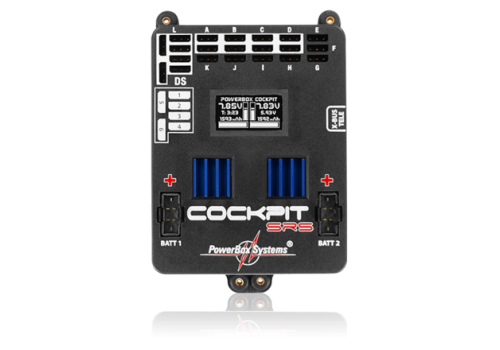
The PowerBox Cockpit SRS is identical in design and construction to the PowerBox Competition SRS, with the addition of one special feature: a freely programmable door sequencer for warbirds or jets.The PowerBox Cockpit SRS 4620 is identical in design and construction to the PowerBox Competition SRS, with the addition of one special feature: a freely programmable door sequencer for warbirds or jets. |
Powerbox Competition and Cockpit SRS Richo from Desert Aircraft Australia takes a look at a couple of the new systems from Powerbox and demonstrates the door sequencing capability. |
Downloads
| Reviews
|
Powerbox - Cockpit SRS Order No.: 4620
- Brand: Powerbox
- Product Code: 4620 Powerbox - Cockpit SRS
- Availability: In Stock
- CMC Product ID: 1095
-
R7,545.00
- Ex Tax: R6,560.87
Related Products
Powerbox - Royal SR2 Order No. 4750
The PowerBox Royal SR2 - professional airborne electronics for the ambitious pilot!Features : 2..
R14,400.00 Ex Tax: R12,521.74
Latest
Toys - RGT EX86160 1/10 LC79 Commander – High-Performance Scale RC Crawler
RGT EX86160 1/10 LC79 Commander – High-Performance Scale RC CrawlerShell Color: YellowDescript..
R10,499.00 R11,126.00 Ex Tax: R9,129.57
Gas Engine - Rubber gs starter (Large) SGS8022
Rubber gs starter (Large cone)SGS8022 (GS Models)..
R79.00 Ex Tax: R68.70
GP 230 cc ( Includes Muffler set)
SPECIFICATIONDisplacement : 230 c.c.Bore : 57 mmRPM Range : 1200-6700Output : 23..
R49,530.00 Ex Tax: R43,069.57
Prop Saver 4mm
4mm Prop Saver - Aluminium collar with screws and O ring for holding Small electric props on indoor ..
R23.00 Ex Tax: R20.00
Sullivan Tailwheel 4-10kg
Steerable Tailwheel Bracket. Springs absorb both ground bumps and steering shocks to protect the mod..
R336.00 Ex Tax: R292.17
Cyano - Zap a gap green (7gr)
Key FeaturesSuperior gap filling formulaMedium viscosityAllow approximately 7 to 10 seconds for part..
R76.00 Ex Tax: R66.09
Dubro # 274 - 4 Pin Spinner, 2 Inc, RED
There's no need to use a hammer, with Dubro's easy on/easy off spinners.Just press-fit t..
R176.00 Ex Tax: R153.04
Xoar - Vortex Electric - 14x10E
Vortex - Electric - 14x10EProp xoar 14x10e vortex glassfibre nylon..
R99.00 Ex Tax: R86.09
FUTABA R7306SB 6-Channel (PWM) / (26-Channel S.BUS) FASSTest - High Gain Aerials
DescriptionThe Futaba R7306SB FASSTest-2.4GHz compatible receiver features bi-directional communicat..
R2,995.00 Ex Tax: R2,604.35
Toys - MN Models MN82S RC Crawler LC79 Toyota Landcruiser PRO version - BLACK
Item no: MN-82SProduct name: 1/12 2.4G full-scale four-wheel drive remote control model car pickup.P..
R1,860.00 Ex Tax: R1,617.39
ARF - Durafly Tundra V3 PNP
After the incredible success of the Tundra V1 and V2, Durafly has decided to produce yet another ver..
R4,589.00 Ex Tax: R3,990.43
Tools - Airbrush hobby compressor with air tank, AS-196
Product name: Twin cylinder mini air compressor with tankType: AS196Features:1. Twin Cylinder Piston..
R2,850.00 Ex Tax: R2,478.26
Ace switch 4 w/fuel dot & 22# 20cm jr/f
Ace switch 4 w/fuel dot & 22# 20cm jr/f..
R519.00 Ex Tax: R451.30
LiPo - 2600mah, 11.1V, 3S, 60C, ManiaX
ManiaX 11.1V 2600mah 30C Lipo Battery Pack : MX2600-3S-303S 2600 mAh 60C - Advanced Seri..
R599.00 Ex Tax: R520.87
ARF - Hacker MXS 804 Racing BLUE
Super aerobatic model for extreme indoor and outdoor aerobatic flying. Model is produced by modern t..
R1,456.00 Ex Tax: R1,266.09
Gas Fuel dots (copper) Haoye
Made of high rigidity aluminum alloy, the fuel filler with fuel dot can directly fill gas for the..
R139.00 Ex Tax: R120.87
Carl Goldberg Spinner, 2-3/4 Inc, YELLOW
Carl Goldberg Spinner, 2-3/4 Inc, YELLOW..
R214.00 Ex Tax: R186.09
Dubro # 275 - 4 Pin Spinner, 2Inc, Yellow
There's no need to use a hammer, with Dubro's easy on/easy off spinners.Just press-fit t..
R176.00 Ex Tax: R153.04
Dubro # 287 - 4 Pin Spinner, 2-1/2Inc, YELLOW
There's no need to use a hammer, with Dubro's easy on/easy off spinners.Just press-fit t..
R218.00 Ex Tax: R189.57
CM8 ( 1/4 32 ) spark plugs - iridium
these CM8 spark plugs for all gas engines. these can be swapped out directly on glow Engines to b..
R360.00 Ex Tax: R313.04
Carbon Fibre Tailwheel - 26cc
Carbon Fiber Tail Wheel Bracket Set with Wheel for 26 / 30cc Gasoline Airplane Specifications..
R373.00 Ex Tax: R324.35
Toys - Wltoys 144001 RC Car, Rear Shocks, 1pc
Toys - Wltoys 144001 RC Car, Front ShocksThese Parts are used for the Wltoys 144001 RC Car Buggy, Wl..
R153.00 Ex Tax: R133.04


